Choose a borehole camera from the deepest interval you must inspect, the smallest clear diameter in the well, the required viewing direction and the evidence you need to record. A down-view probe is useful for general descent and obstructions; side-view or rotating 360° imaging is stronger for casing joints, cracks and wall conditions. Specify cable length with a practical reserve, confirm probe pressure rating and diameter, and require depth-synchronized video when the inspection must support repair or acceptance decisions.
A borehole camera lets an operator see conditions that cannot be confirmed from the surface: casing joints, corrosion, cracks, encrustation, sediment, obstructions, water-entry zones and the general state of an open hole. The image is valuable only when the camera can safely reach the target depth and the recorded position can be related to the well construction log.
The best system is therefore not simply the camera with the longest cable or largest screen. A useful configuration matches well depth, casing diameter, water clarity, probe geometry, lighting, cable strength, recording format and field handling. This guide explains how to prepare that specification and how to produce an inspection that another technician can understand later.
What a water well inspection camera can—and cannot—show
A camera provides direct visual evidence of surfaces that are visible in the water column. In a cased well it can document joint alignment, holes, corrosion, deposits, deformation and objects lodged inside the casing. In an open borehole it may show fractures, cavities, bedding, unstable zones and points where particles or water movement are visible.
Video does not measure sustainable well yield, water chemistry or the full condition behind an opaque casing wall. Turbid water, suspended sediment, biological growth and reflections can hide defects. Combine video with the construction record, water-level measurements, pumping behavior, water-quality tests and other logging methods when the decision requires more than a visual inspection.
| Inspection objective | Useful camera evidence | Additional evidence often needed |
|---|---|---|
| Casing condition | Joints, corrosion, holes, deformation and deposits | Construction log, caliper or repair history |
| Obstruction | Object shape, depth and available clearance | Fishing-tool dimensions and well completion details |
| Open-hole geology | Visible fractures, cavities, bedding and loose material | Driller log and geophysical borehole logs |
| Water-entry interval | Visible inflow, particles or changes near fractures | Flow logging, pumping test and water levels |
| Well acceptance | Recorded condition and depth before handover | Contract specification, depth check and performance test |
Seven factors that determine the right borehole camera
Maximum inspection interval
Specify the deepest point that must be recorded and add a sensible handling reserve rather than selecting cable length from total well depth alone.
Smallest clear opening
Check casing, pump column, centralizers and restrictions. The probe must pass the narrowest verified clearance without forcing.
Down, side or rotating
Match the viewing direction to the job: descent and obstructions, detailed casing walls, or both.
Clarity and pressure
Deep water increases pressure; cloudy water reduces useful viewing distance. Confirm the rated working depth and lighting control.
Load-bearing and marked
The cable must support the probe, resist abrasion and provide readable depth references or an electronic counter.
Video and still evidence
Confirm resolution, storage, time stamp, file export and whether depth can be shown or narrated in the recording.
Reel, power and transport
Consider battery duration, vehicle power, sun visibility, reel braking, cleaning and the weight one operator can manage.
Down-view, side-view or rotating 360° camera?
A down-view camera looks ahead during descent. It is efficient for checking whether the path is open, seeing the bottom, locating dropped objects and observing large changes in diameter. Because the lens faces downward, fine vertical cracks or casing-wall defects can pass near the edge of the image.
A side-view lens looks directly at the wall. A motorized rotating probe allows the operator to scan the full circumference at a selected depth, which is helpful for casing joints, perforations, corrosion, cracks and open-hole structures. Rotation is most useful when movement is slow and the operator records orientation and depth consistently.
| Camera view | Best suited to | Main limitation |
|---|---|---|
| Down-view | Descent, bottom condition, obstructions and general inspection | Less detail on the full casing circumference |
| Fixed side-view | Focused wall and joint inspection | Orientation can be difficult to reproduce |
| Rotating 360° side-view | Systematic casing, fracture and perforation inspection | Requires slower operation and orientation control |
| Dual-view system | Projects needing descent awareness and detailed wall evidence | More components and configuration to confirm |
How to specify depth, probe size, cable and lighting
Start with the as-built well log, not the nominal drilling depth. Record the casing inside diameter, liner changes, pump position, known restrictions, static water level and total accessible depth. If the pump remains installed, calculate the actual annular clearance and do not lower a probe into a space where it can wedge between the pump column and casing.
Cable length should exceed the planned inspection depth enough to allow safe connection and reel handling, but an unnecessarily long reel adds weight and setup time. At greater depths, cable stretch, reel counting and deviation can affect the displayed position. Use clear depth marks, verify the counter at the surface and narrate important depths in the video.
- Confirm probe outside diameter, length and minimum bend clearance.
- Confirm the pressure or working-depth rating for the complete probe and connector assembly.
- Use adjustable lighting to control reflection from white PVC, stainless steel and suspended particles.
- Choose a centralizer when it improves wall distance without increasing snag risk.
- Check cable markings, electronic depth-counter resolution and the reference point used for zero.
- Confirm storage media, video format, date/time settings and file export before field deployment.
Step-by-step borehole video inspection workflow
Review the well record
Collect total depth, casing sizes, screened intervals, pump position, previous repairs and the inspection objective.
Make the well safe
Isolate electrical and mechanical equipment, secure the work area and confirm whether the pump must be removed by qualified personnel.
Check and clean the system
Inspect the probe window, seals, connector, cable, reel, depth counter, storage and power before lowering anything.
Set the depth reference
Choose a fixed measuring point at the wellhead, set zero and record it in the job notes and opening video.
Lower slowly
Watch the down-view image, avoid sudden loading and pause at casing joints, water level, screens and any change in condition.
Inspect the wall
At important depths, stop vertical movement and rotate or orient the side-view camera systematically.
Repeat critical intervals
Revisit uncertain defects at slower speed, with adjusted lighting and a second viewing direction when available.
Recover and document
Reel in smoothly, clean and disinfect as required, back up the files and create a depth-indexed observation log.
How to read and report borehole camera video
Separate observations from interpretations. An observation might be “dark horizontal opening at 74.6 m with particles moving toward it.” An interpretation might be “possible water-entry fracture.” Keeping those statements separate prevents a visual impression from becoming an unsupported conclusion.
Use the same naming convention throughout the report and include representative still frames with depth, viewing direction and comments. If the displayed depth may be affected by cable stretch or an uncertain reference, state the tolerance. Record intervals that could not be evaluated because of turbidity, reflection or obstruction.
- Well identification, date, operator and inspection objective
- Depth reference, accessible depth and water level at the time of inspection
- Camera model, probe type, cable length, lighting and recording settings
- Depth-indexed casing, screen, geology, obstruction and water-movement observations
- Representative images plus the original continuous video files
- Limitations, uncertain intervals and recommended next checks
Common borehole camera mistakes to avoid
- Selecting the probe before checking the smallest clear well diameter.
- Assuming total drilling depth equals the accessible inspection depth.
- Lowering beside installed equipment without a verified clearance and recovery plan.
- Using maximum light in cloudy water and creating reflection instead of visibility.
- Descending too quickly to inspect joints, screens or narrow fractures.
- Reporting displayed depth without identifying the zero reference.
- Saving only short phone recordings instead of the original inspection files.
- Treating video alone as proof of well yield, water quality or hidden casing condition.
PQWT borehole camera configurations to consider
The standard configuration should be confirmed from the project depth, minimum diameter, required viewing direction and recording needs. Deeper reels and rotating-probe options may change the complete package, shipping dimensions and operating procedure.
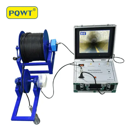
200 m borehole inspection camera
Full-HD recording, depth measurement and down-view or rotating 360° probe options for water wells and engineering boreholes.
View product →Compare 200–2,000 m configurations
Review camera depth, probe, DVR, cable reel and rotating-view options for well and borehole inspection projects.
View product →Frequently asked questions
What cable length should I choose for a borehole camera?+
Choose a length that safely exceeds the deepest accessible inspection interval and allows practical wellhead handling. Use the as-built well log and add a modest reserve; do not assume total drilling depth is fully accessible.
Is a 360° camera better than a down-view camera?+
They answer different questions. Down-view is useful during descent and for obstructions or the well bottom. Rotating side-view imaging is stronger for detailed casing walls, joints, cracks and fractures. A dual-view configuration may be best when both are required.
Can a borehole camera find groundwater?+
It can show visible water movement, fractures and downhole conditions inside an existing open well, but it does not survey undrilled ground or guarantee aquifer yield. Pumping tests and hydrogeological evidence are still required.
Can the camera inspect a well with the pump installed?+
Only when the actual clearance, cable path and recovery risk have been assessed. A probe can become trapped beside pump equipment, so removal by qualified personnel is often the safer inspection plan.
What information is needed for a borehole camera quotation?+
Provide total and accessible depth, casing inside diameter, pump status, water clarity, required down-view or 360° imaging, recording needs, power conditions, destination and quantity.
PROJECT REVIEW & MODEL SELECTION
Need a borehole camera configuration for your well?
Send the well depth, minimum casing diameter, pump status, water clarity and required viewing direction. We will confirm the probe, cable reel, recording configuration, shipping and export quotation.