Measure every water level from the same surveyed reference point at the wellhead. Lower a clean probe slowly until the audible or visual contact signal activates, lift and repeat to confirm, then read the graduated tape at the reference point. Record time, pumping status and units. Static level is measured after adequate recovery; pumping level is measured while discharge is stable. Drawdown equals pumping depth to water minus static depth to water.
A water-level measurement looks simple, but a small change in reference point, tape tension or timing can create a false trend. Reliable groundwater records depend on a fixed datum, a clear measurement procedure and notes that explain whether the well was resting, pumping or recovering.
Portable electric contact meters use a probe connected to a marked tape. When the probe touches water, the circuit activates a light and/or buzzer. The operator reads depth to water at the wellhead reference. This guide covers field preparation, static and pumping measurements, drawdown, recovery and equipment selection.
Static water level, pumping level, drawdown and recovery
Depth to water is the vertical distance from the chosen measuring reference point down to the water surface. A larger depth reading means the water surface is lower. Water-level elevation is calculated by subtracting depth to water from the surveyed elevation of the reference point.
Static water level is the level after the well has recovered sufficiently from pumping or other disturbance. Pumping water level is the level observed while the well is discharging at a stated rate. Drawdown is the difference between the pumping and static depths to water. Recovery describes the return toward the pre-pumping level after the pump stops.
| Term | Meaning | Required field note |
|---|---|---|
| Static water level | Depth to water after adequate rest/recovery | Last pumping time and recovery condition |
| Pumping water level | Depth to water while pumping | Discharge rate and elapsed pumping time |
| Drawdown | Pumping depth minus static depth | Both readings from the same reference point |
| Recovery level | Depth to water after pumping stops | Elapsed recovery time for each reading |
| Water-level elevation | Reference elevation minus depth to water | Surveyed datum and consistent units |
Establish one fixed measuring reference point
Select a permanent, accessible point on the casing or measuring port. Mark it clearly and describe it in the field form—for example, “top of north side of steel casing.” If groundwater elevation will be compared between wells, survey the elevation of that exact point to a common datum.
Never switch casually between ground level, casing top and a pump-plate opening. If the measurement must be taken from a temporary point, measure the vertical offset to the established datum and record the correction. Keep the tape vertical and use the same units throughout the project.
Mark the exact point
A painted notch or documented casing point makes repeated measurements comparable.
Record any correction
If the probe enters through a point above or below the datum, measure and apply the vertical offset.
Do not mix scales
Record metres and millimetres or feet and hundredths consistently, including calculated drawdown.
Water level is time-dependent
Note date, time, recent pumping, nearby pumping, rainfall and other conditions that may affect comparison.
Step-by-step static water-level measurement
Confirm the well is resting
Record when pumping stopped and whether nearby wells or equipment may still influence the level. Required recovery time depends on the aquifer and well.
Inspect the measuring path
Check that the access port is open and the probe cannot catch on wires, pipes, pump equipment or sharp casing edges.
Test the meter
Check the battery, light and buzzer with clean water or the manufacturer’s approved test method before lowering the probe.
Set the reference
Place the tape against the documented reference point and keep the reel aligned so the tape enters vertically.
Lower the probe slowly
Approach the expected level carefully. Stop at the first stable audible/visual signal rather than allowing a long length of probe and tape to submerge.
Confirm the contact
Raise the probe until the signal stops, then lower it again. Repeat until the contact depth is consistent.
Read and record
Read the tape at the reference point to the meter’s practical resolution and record depth, units, time and well condition.
Recover the tape safely
Reel evenly, inspect for damage and clean the wetted probe and tape according to the monitoring protocol.
How to measure pumping level and calculate drawdown
Take a confirmed static reading before the pumping period when the test design requires it. Start the pump, record the discharge rate and measure depth to water at planned elapsed times. Early readings may be frequent because the water level can change rapidly; later intervals can be increased as the response stabilizes.
Use the same reference and correction for every reading. Drawdown is calculated as pumping depth to water minus static depth to water. For example, if static depth is 18.42 m and pumping depth is 27.86 m, drawdown is 9.44 m. Always report the discharge rate and elapsed pumping time with the drawdown value.
| Measurement | Example | Calculation or meaning |
|---|---|---|
| Static depth to water | 18.42 m | Confirmed before pumping |
| Pumping depth to water | 27.86 m | At the stated rate and elapsed time |
| Drawdown | 9.44 m | 27.86 m − 18.42 m |
| Reference elevation | 126.35 m | Surveyed elevation of measuring point |
| Static water elevation | 107.93 m | 126.35 m − 18.42 m |
- Secure the tape so it cannot be pulled into moving pump equipment.
- Keep discharge as stable as the test requires and record every rate change.
- Use a guide tube when turbulence, casing flow or installed equipment prevents a stable contact.
- Do not compare readings taken from different wellhead points without an offset correction.
- Follow the pumping-test plan and local requirements when results will support a yield decision.
Measure water-level recovery after pumping stops
Recovery data shows how the water level rises after discharge ends and can support evaluation of well and aquifer response. Record the exact pump-stop time. Measure at planned elapsed times using the same reference point, with frequent readings at the beginning if the level changes quickly.
Continue until the target recovery criterion or monitoring period is reached. Do not describe the final reading as fully recovered unless the defined criterion has been met. Nearby pumping, barometric effects, rainfall and changing discharge before shutdown may influence the curve and should be noted.
- Record the final pumping level, discharge rate and exact shutdown time.
- Begin recovery measurements at the intervals specified by the test plan.
- Repeat any reading that changes unexpectedly or produces an unstable contact signal.
- Record elapsed time as well as clock time to prevent later calculation errors.
- Plot depth to water or residual drawdown against time only after checking reference and units.
Improve accuracy and recognize false readings
The tape graduation may be finer than the practical accuracy of the complete measurement. A moving water surface, angled tape, wet probe, cable stretch, uncertain reference and operator reading can introduce error. Report only the precision justified by the field condition.
A signal above the expected water level may come from condensation, wet casing, conductive foam or contact with wet equipment. Raise and lower the probe to confirm a repeatable transition. If the tape rubs on the casing, reposition it without changing the reference height.
- Test the battery and contact circuit before and after a measurement round.
- Approach the water surface slowly and minimize probe submergence.
- Repeat the contact at least once and investigate differences larger than the project tolerance.
- Keep tape tension consistent without stretching or sharply bending the marked tape.
- Use a dedicated guide tube in pumped wells when safe and appropriate.
- Record inaccessible, turbulent or uncertain readings instead of inventing precision.
Cleaning, decontamination and meter care
Groundwater monitoring equipment can transfer sediment, microorganisms or contaminants between wells. Follow the project’s decontamination procedure and any local environmental requirements. Use compatible cleaning materials so the probe, tape markings, seals and cable are not damaged.
After use, dry the tape while rewinding it evenly. Inspect the probe, splice, conductor, reel brake and markings. Store the meter clean and dry with the battery condition checked. Repair damaged tape or insulation before the next field job rather than relying on an intermittent contact signal.
How to choose a water level meter for wells
Choose tape length from the greatest expected depth to water—not only the total well depth—and allow practical handling reserve. Confirm probe diameter against the access tube, graduation, audible/visual indication, reel material, power, replacement parts and the required cleaning protocol.
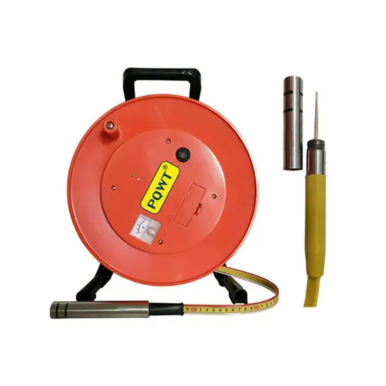
30–500 m cable options
Portable steel-tape meters with a stainless-steel probe, 1 mm graduation, audible/visual indication and field reel configurations.
View product →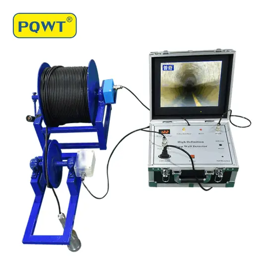
Combine level and visual inspection
Use a water-level meter for repeatable depth readings and a borehole camera when the project also requires visual casing or obstruction evidence.
View product →Frequently asked questions
What is the difference between static and pumping water level?+
Static water level is measured after the well has adequately recovered without pumping. Pumping water level is measured while the well discharges at a recorded rate and elapsed time. Their difference in depth is drawdown.
How long should a well rest before measuring static level?+
There is no universal time. Recovery depends on the well, aquifer and previous pumping. Use the project protocol, review recovery behavior and record the actual time since pumping stopped.
How do I calculate well drawdown?+
Subtract static depth to water from pumping depth to water, using the same reference point and units. A static depth of 18.42 m and pumping depth of 27.86 m gives 9.44 m of drawdown.
Why does the water level probe signal before reaching the water?+
Condensation, a wet casing, conductive foam or contact with wet equipment can activate the circuit. Raise and lower the probe to find a repeatable transition and inspect the measuring path.
What cable length water level meter should I buy?+
Choose a tape longer than the greatest expected depth to water with a practical reserve. Also confirm probe diameter, graduation, reel handling, cleaning requirements and whether pumped-well measurements need a guide tube.
PROJECT REVIEW & MODEL SELECTION
Need a water level meter for a well or monitoring project?
Send the maximum expected depth to water, access-tube diameter, measurement purpose, required cable length, destination and quantity. We will confirm a suitable configuration and export quotation.