Use an electromagnetic utility locator by applying a known transmitter signal to the target whenever possible, then trace the receiver response from a confirmed starting point. Direct connection normally provides the most selective signal, a clamp is useful when the conductor is accessible but cannot be disconnected, and induction is used when connection is unavailable. Mark the route from repeated peak/null evidence, verify from both directions and treat displayed depth as an estimate that must be checked before excavation.
Buried utility locating is not the same as detecting a water leak. A pipeline and cable locator traces an electrically conductive path or a tracer conductor; a leak detector listens for escaping water or uses another leak-specific method. Knowing which question the instrument answers prevents expensive searching in the wrong place.
Electromagnetic locating systems combine a transmitter and receiver. The transmitter places a selected frequency on a metallic pipe, cable or tracer wire, and the receiver follows the resulting field above ground. Signal quality depends on connection, grounding, frequency, nearby conductors, depth and site interference. A reliable survey builds route evidence instead of trusting one screen reading.
How an electromagnetic pipe and cable locator works
Alternating current on a conductor creates an electromagnetic field around it. A locator receiver detects that field and indicates signal strength, direction or other guidance depending on the model. The operator moves along the probable route, maintains receiver orientation and marks a series of confirmed positions.
The receiver does not identify material by sight. A strong signal may be the intended pipe, a bonded neighboring cable, a fence, a parallel utility or a distorted return path. Begin at a known access point, confirm that the signal behaves as expected and continuously check whether the traced route fits plans, visible fittings and site logic.
Direct connection, signal clamp, induction and passive scan
Use the most selective safe connection available. Direct connection applies the transmitter lead to an accessible conductor with a separate ground return and usually produces the clearest target signal. It must be performed only at approved access points and in accordance with electrical and utility safety procedures.
A signal clamp couples the transmitter signal around an accessible cable or pipe without a bare-metal connection. Induction places the transmitter above the assumed route and energizes nearby conductors through the field; it is convenient but more likely to couple onto multiple utilities. Passive receiver modes search for existing power or radio-frequency energy but may miss quiet or well-shielded utilities.
| Method | Best use | Main caution |
|---|---|---|
| Direct connection | Accessible known metallic target | Requires approved connection and a good ground return |
| Signal clamp | Accessible cable or pipe that should not be disconnected | Clamp must fully close and the circuit must support signal flow |
| Induction | No safe access point or rapid area tracing | Signal can couple to several nearby conductors |
| Passive power mode | Energized power cables carrying detectable current | No response does not prove a cable is absent |
| Passive radio mode | Long conductive utilities receiving radio energy | Coverage and target selectivity vary by site |
| Sonde tracing | Non-metallic drains, ducts or pipes with internal access | Tracks the sonde position, not the entire pipe automatically |
Choose transmitter frequency from the connection and site
Lower frequencies generally travel farther on a well-connected conductor and are less likely to jump onto adjacent utilities, but they need a good circuit and may be weak on poorly bonded or short targets. Higher frequencies can couple more easily across imperfect connections and may help on difficult targets, but they also increase bleed-over to nearby conductors and surface objects.
Start with the lowest frequency that produces a stable, traceable response, then change only for a reason. If a higher frequency creates several apparent routes, return to the known point, improve the connection or ground and compare the response. Record the selected frequency and connection method with the route notes.
Selective, longer-path tracing
Often preferred for a continuous well-grounded target when interference and coupling must be minimized.
General field compromise
Useful when the circuit is adequate but a very low frequency produces insufficient response.
Easier coupling, more bleed-over
May help a difficult connection but can energize neighboring conductors and confuse route selection.
Useful screening, not clearance
A passive scan can reveal energized or re-radiating utilities but cannot demonstrate that the ground is free of utilities.
Step-by-step underground utility tracing workflow
Review records and site evidence
Collect drawings, utility-owner information, access points, surface features and the planned work area before using the locator.
Complete a broad safety scan
Use appropriate passive modes and visual inspection to identify obvious energized or re-radiating conductors. Follow local locating and permit requirements.
Identify the target
Choose a confirmed valve, cable access, tracer-wire terminal or other approved point and understand how it connects to neighboring systems.
Apply the transmitter signal
Prefer direct connection, then clamp, using induction when connection is unavailable. Place the ground to support a useful return path.
Confirm near the access point
Check signal strength, direction and receiver response on the known target before walking away from it.
Trace in short sections
Keep the receiver vertical and orientation consistent. Mark repeatable positions and investigate sudden turns or signal changes.
Cross-check the route
Approach from both sides, use peak/null or directional evidence available on the instrument and compare another frequency if needed.
Mark and document
Mark the route, estimated depth, connection method, frequency, confidence and any unresolved parallel or crossing utilities.
How to check utility depth without overtrusting the display
Depth calculation assumes a reasonably shaped field from a single target and correct receiver position. Hold the receiver vertically over the confirmed route, align it as instructed for the model and take more than one reading. Repeat a short distance along the line and compare the results.
Distorted fields from bends, tees, parallel conductors, poor grounding, nearby metal or excessive signal can produce a plausible but incorrect number. A depth value should support route evidence, not replace it. For excavation, follow the applicable tolerance zone, safe digging practice and physical verification requirements such as approved vacuum or hand exposure.
- Measure only after the route has been confirmed from multiple positions.
- Keep the receiver vertical and directly over the center response.
- Move slightly along the route and repeat rather than relying on one depth reading.
- Reduce excessive signal or change connection when the field appears broad or distorted.
- Treat abrupt depth changes as a reason to investigate bends, crossings or interference.
- Never use an electronic depth estimate as authorization for mechanical excavation clearance.
Difficult targets: plastic pipe, parallel utilities and congested sites
A non-metallic pipe needs a tracer wire, inserted sonde or another conductive element to be located electromagnetically. If a water-service tracer wire is broken, the signal may stop at the break or couple onto another grounded object. Acoustic pipe-location, ground-penetrating radar or other methods may be considered depending on material, access and site conditions.
In a congested corridor, direct connection and lower frequency can improve selectivity. Observe current direction or guidance features when available, trace from both ends and compare the expected termination. A route that suddenly leaves the expected corridor or continues beyond a known endpoint may be a coupled conductor rather than the target.
| Problem | Likely cause | Useful response |
|---|---|---|
| Signal splits into two routes | Coupling to a branch or parallel conductor | Improve direct connection, lower frequency and trace both paths |
| Signal disappears | Open tracer, insulated joint, poor return or target end | Check connection, ground, access points and trace from the other end |
| Very broad peak | Excessive output, deep target or field distortion | Reduce output, cross-sweep and compare another position |
| Route moves toward a fence | Unwanted coupling to surface metal | Relocate transmitter/ground and use a more selective connection |
| Plastic pipe has no response | No conductive tracer or sonde | Use an approved tracer/sonde or another locating technology |
Common utility-locating mistakes that create false marks
- Beginning far from a confirmed target instead of validating the signal at an access point.
- Using induction in a congested area without checking which conductor received the signal.
- Selecting a high frequency by default and following bleed-over onto a neighboring utility.
- Holding the receiver tilted or changing orientation during route and depth checks.
- Marking a route from signal strength alone without direction, cross-sweep or repeat evidence.
- Assuming a passive-mode silence proves that no utility is present.
- Trying to trace plastic pipe that has no conductive tracer or internal sonde.
- Treating the displayed depth as exact excavation clearance.
Choosing between PQWT GX700, GX800 and GX900
Choose the system from target type, required depth range, route complexity, frequency flexibility, fault-analysis needs and operator workflow. The figures below summarize the current website positioning; confirm the transmitter, receiver, accessories and final specification in the formal quotation.
| Model | Positioning | Website specification summary |
|---|---|---|
| GX700 | Portable routine pipeline and cable tracing | Path tracing and depth measurement, stated up to 6 m |
| GX800 | Multi-frequency work in more complex utility corridors | Visual guidance and multi-frequency locating, stated up to 6 m |
| GX900 | Higher-power professional and deeper/longer-distance work | Path, depth and fault-analysis functions, stated up to 8 m |
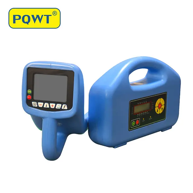
Portable pipeline and cable locator
For routine metallic utility path tracing and depth checks with a stated locating range up to 6 m.
View product →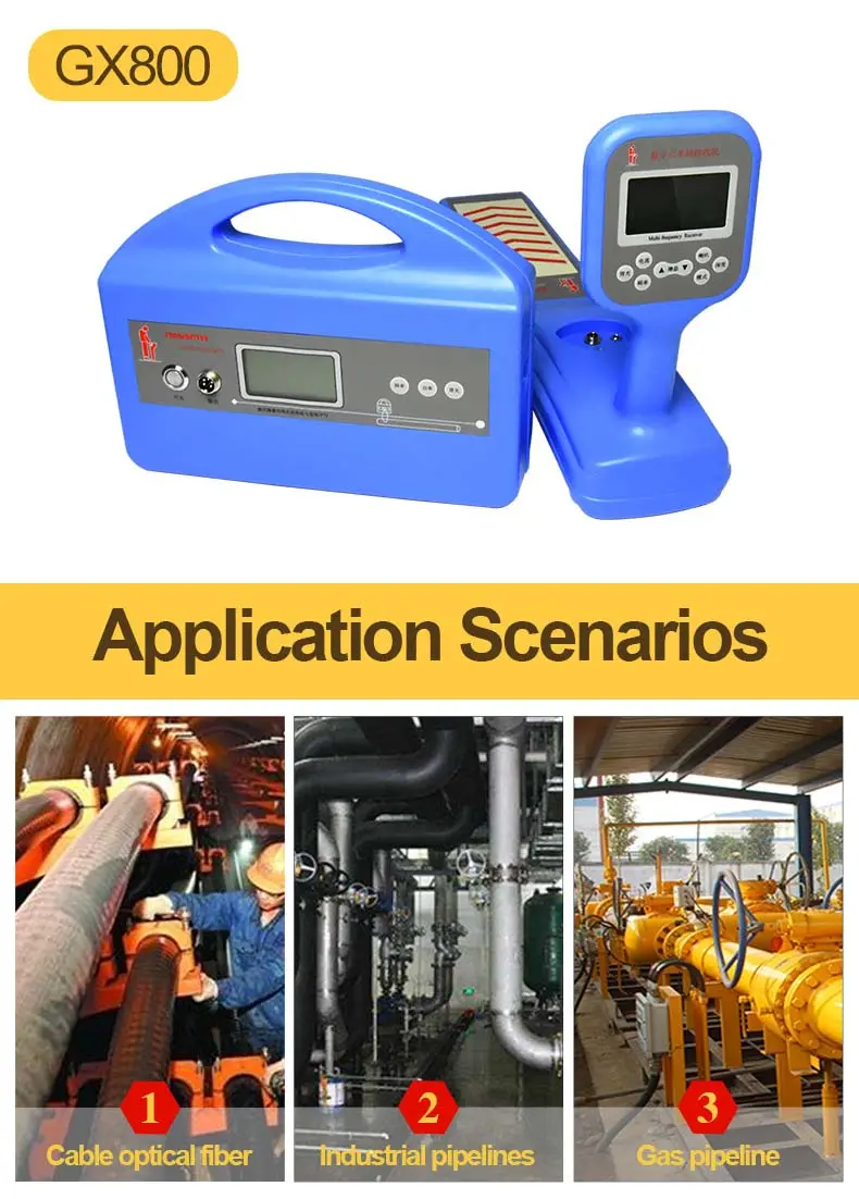
Multi-frequency utility locator
For complex and parallel utilities requiring frequency selection and intelligent signal visualization.
View product →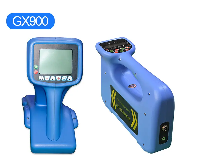
Professional high-power locator
For deeper or longer metallic routes and projects requiring additional fault-analysis capability.
View product →Frequently asked questions
Can a utility locator find plastic water pipes?+
Not from the plastic wall alone. Electromagnetic locating requires a conductive tracer wire, an inserted sonde or another conductor associated with the pipe. Where none exists, a different locating method may be needed.
What is the best way to connect a pipe locator transmitter?+
Direct connection to an approved accessible conductor is normally the most selective. A clamp is useful when disconnection is not appropriate, while induction is less selective and can energize several nearby utilities.
Which transmitter frequency should I use?+
Start with the lowest frequency that gives a stable trace on a good connection. Increase it only when the target or circuit requires easier coupling, while checking carefully for bleed-over onto neighboring conductors.
Is the depth shown by an underground cable locator exact?+
No. It is an estimate based on field geometry and can be distorted by bends, tees, parallel conductors, nearby metal, grounding and signal level. Repeat the reading and physically verify according to safe excavation rules.
How do I choose GX700, GX800 or GX900?+
Provide the target utility, material, expected depth, route length, access points, site congestion, required frequency or fault-analysis functions, destination and quantity. The final configuration should be confirmed in a formal quotation.
PROJECT REVIEW & MODEL SELECTION
Need help choosing a pipeline and cable locator?
Send the target material, expected depth, route length, available access points, nearby utilities and required functions. We will compare GX700, GX800 and GX900 and confirm the export configuration.