Choose an underground water detector by matching its configured survey range, acquisition method, display workflow and channel capacity to the project—not simply by buying the deepest model. In the field, collect repeatable measurements along well-planned lines, compare curves and geological profiles, cross-check anomalies and combine the results with local hydrogeology before selecting a drilling point.
Groundwater exploration is not only about finding a colored anomaly on a screen. A useful survey begins with a clear geological question: Are you looking for a weathered zone, a water-bearing fracture, a fault contact, a buried valley or another structure that may store and transmit groundwater?
A professional groundwater detector helps organize field measurements into curves and profile maps so the operator can compare changes along a survey line. It provides evidence for borehole siting, but drilling remains the final verification.
What an underground water detector actually shows
PQWT groundwater survey instruments collect electrical field measurements and process them into curves and geological profile images. The operator studies how values change from point to point and looks for consistent anomalies that may correspond to geological boundaries, fractures, weathered zones or water-related structures.
The screen does not directly photograph an underground aquifer. A low-value or high-contrast anomaly can have more than one cause. Clay, mineralized ground, saline water, metal interference and changing surface conditions may influence readings.
Seven factors to consider before choosing a model
Target survey depth
Estimate the expected aquifer and drilling depth from nearby well records. Select a suitable range with margin instead of choosing maximum depth without geological justification.
Project complexity
A farm well and a regional hydrogeological project require different acquisition density, survey lines and reporting detail.
Channel configuration
Portable automatic-mapping models suit straightforward surveys. Multi-channel systems support denser acquisition and more complex geological cross-checking.
Field workflow
Choose between an integrated touchscreen, mobile-app operation or a larger professional display according to the operator and site conditions.
Terrain and access
Consider carrying distance, slope, vegetation, cable layout, electrode contact and the number of people available for field work.
Data interpretation
Automatic maps make results easier to review, but training and geological judgment are still necessary for responsible borehole siting.
Support and training
Confirm operating guidance, remote interpretation support, warranty, accessories and replacement parts before purchase.
How to compare PQWT groundwater detector series
The best series depends on how the instrument will be used. The following comparison is a practical selection framework rather than a substitute for model-specific confirmation.
| Series | Typical workflow | Best suited to |
|---|---|---|
| M Series | Smartphone-linked operation with automatic curves and profile mapping | Portable surveys, lighter field kits and users who prefer an Android-app workflow |
| TC Series | Portable automatic mapping with integrated field operation | Routine groundwater prospecting, borehole siting and drilling preparation |
| S Series | Touchscreen automatic mapping with multiple depth configurations | Professional field teams requiring an integrated display and clear profile output |
| GT Series | Multi-channel geological exploration and high-resolution acquisition | Larger, deeper or more complex surveys requiring denser measurements and geological comparison |
Start with the project—not the maximum depth
Send the target depth, geology, nearby well records and expected survey area for a suitable configuration recommendation.
Step-by-step groundwater survey workflow
1. Collect local information before the survey
Record the depth, yield and geological logs of nearby wells whenever available. Review terrain, valleys, exposed rock, faults, drainage, land access, power lines and underground utilities. This information helps select survey direction and prevents avoidable interference.
2. Plan the survey line
Choose a line that crosses the expected geological structure rather than following it. Keep the line as straight as practical. Mark stations at consistent spacing and record the start point, direction and station numbers so the survey can be repeated.
3. Prepare electrodes, cables and instrument
Confirm battery charge, accessories and model settings. Install electrodes firmly and maintain stable contact with the ground. Loose connections, dry surface contact or inconsistent cable placement can create false changes between points.
4. Collect stable measurements
Follow the same procedure at every station. Avoid touching connections during acquisition. If a reading changes unexpectedly, check the electrode, cable and environment, then repeat the measurement before moving on.
5. Add cross-lines where needed
A single profile may show an anomaly but not its direction or extent. A cross-line or parallel line helps determine whether the feature is repeatable and structurally consistent. Complex projects should use enough lines to understand the target in more than one direction.
6. Save field notes with the data
Record station spacing, line direction, terrain, weather, nearby infrastructure, electrode conditions and unusual readings. Good field notes make later interpretation more reliable and allow another operator to reproduce the survey.
How to interpret curves and geological profiles
Begin with the overall trend before focusing on one color or one point. Look for zones where multiple frequencies, adjacent stations or separate survey lines show a consistent change. Compare the anomaly width, shape, continuity and position with the expected geological structure.
Measure it again
A real subsurface feature should remain recognizable when the station is rechecked under the same conditions.
Compare nearby points
Geological structures normally influence a zone. Treat a single isolated spike with caution until connections and interference are checked.
Use another line
Cross-lines help determine whether the anomaly continues in a meaningful structural direction.
Match the geology
Use well logs, outcrops, terrain and regional hydrogeology to decide which interpretation is most reasonable.
Actual groundwater level, drilling depth, yield and water quality can only be confirmed after drilling and testing. Avoid presenting an instrument image as a guaranteed flow-rate or water-quality result.
Common mistakes that reduce survey reliability
- Buying the deepest model without confirming the realistic drilling target.
- Using only one short survey line and selecting the strongest color immediately.
- Changing station spacing or measurement procedure partway through a line.
- Ignoring poor electrode contact, damaged cables or unstable connections.
- Surveying too close to power lines, buried metal, fences, pumps or other interference.
- Failing to record the line direction, station numbers and unusual field conditions.
- Assuming every low-value anomaly is groundwater while ignoring clay or mineralization.
- Promising exact groundwater yield before drilling and conducting a pumping test.
Underground water detector models to consider
These four configurations illustrate different workflows. Confirm the final model and accessories according to the target depth, geology and project scale.
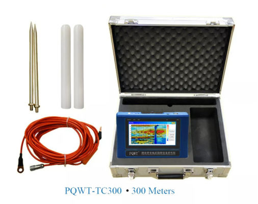
Portable automatic mapping
A 300 m configuration for practical borehole siting with curves and geological profile output.
View product →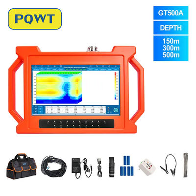
Multi-channel geological survey
A 500 m professional system with high-resolution acquisition and a 10.1-inch field display.
View product →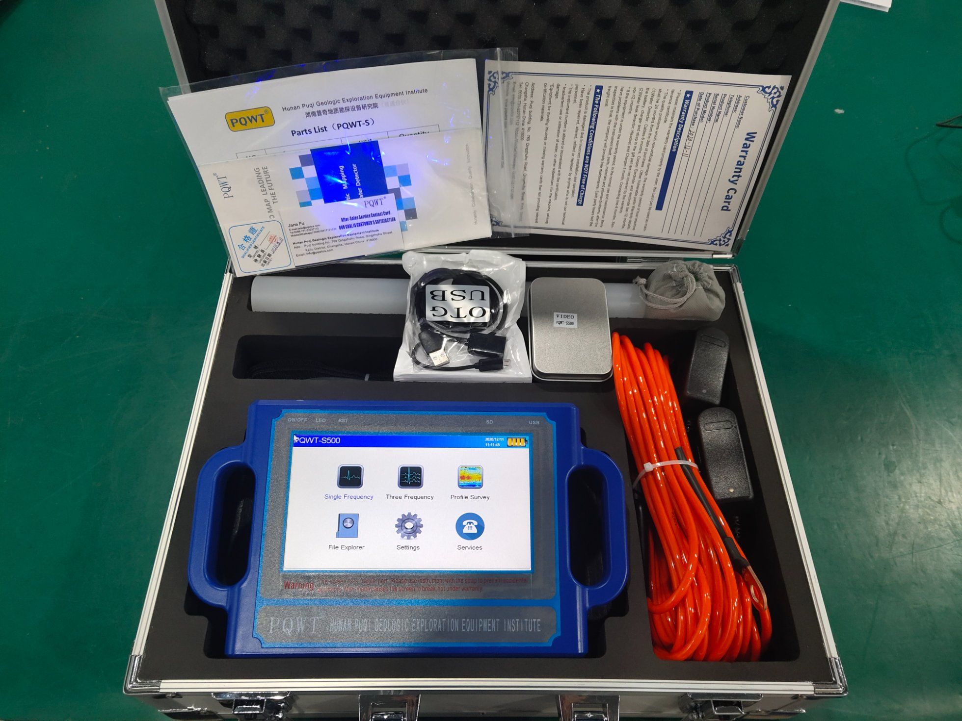
Touchscreen field workflow
A 500 m automatic-mapping model with an integrated touchscreen workflow for field surveys.
View product →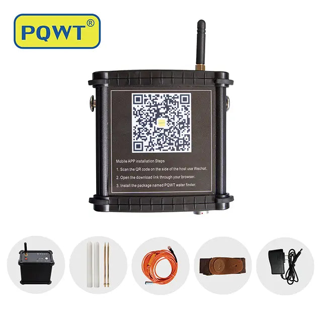
Mobile-app groundwater survey
A smartphone-linked 400 m configuration for portable automatic curves and profile mapping.
View product →For a complete overview, visit our underground water detector collection.
Frequently asked questions
How deep should my underground water detector be able to survey?+
Choose a detector whose configured survey range covers the expected aquifer and drilling depth, with reasonable margin. The deepest model is not automatically the best choice; local geology, project scale, data quality and operator experience are equally important.
Can a groundwater detector guarantee that drilling will produce water?+
No geophysical instrument can guarantee a successful well by itself. Detector results should be combined with local geology, nearby well records, terrain, hydrogeological knowledge and repeat survey lines before selecting a drilling point.
Does the instrument directly show groundwater depth and flow rate?+
The instrument displays measured curves and geological profile anomalies that help the operator infer promising structures. Actual water depth, yield and water quality are confirmed by drilling, logging and pumping tests.
What is the difference between portable, touchscreen and multi-channel models?+
Portable and mobile-app models favor light field work and simpler surveys. Touchscreen automatic-mapping models provide an integrated workflow. Multi-channel geological systems are better suited to larger or more complex projects requiring denser acquisition and cross-checking.
PROJECT REVIEW & MODEL SELECTION
Need help choosing a groundwater detector?
Send the country, target depth, geological conditions, nearby well information, survey area and required quantity. Our team will recommend a suitable series and configuration.