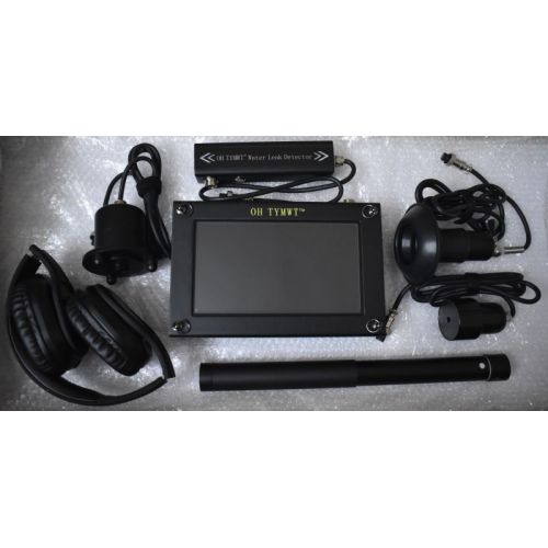
There is no single best leak-detection method for every pipe. Use flow and pressure evidence to confirm loss, map and isolate the network, then choose a pinpointing method. Acoustic listening is often the first choice for pressurized pipes with usable leak noise. Correlation helps on accessible pipe sections, noise loggers screen larger networks, and tracer gas is valuable for quiet leaks or plastic pipes. Thermal imaging and inspection are supporting methods rather than universal substitutes.
A leak-detection instrument is most effective when it answers a defined stage of the job. Some tools indicate that a network is losing water, some narrow the faulty section and others help choose the excavation point. Confusing those stages leads to false confidence and unnecessary digging.
The correct method depends on pipe material, pressure, diameter, burial depth, surface, access points, background noise, water availability and repair risk. Professional teams often combine two or more methods because independent signals reduce uncertainty.
Separate confirmation, localization and pinpointing
A strong night-flow anomaly may prove that a zone is losing water but cannot reveal the exact point. A loud ground signal may suggest an excavation zone but should still be checked against the mapped route and section evidence. Write down what each measurement proves and what it does not.
Is water being lost?
Meter flow, night-flow analysis, pressure behavior, tank level and consumption history can confirm abnormal use.
Which section is affected?
Valve isolation, district metering, contact listening and noise logging narrow a large network to a manageable area.
Where should repair start?
Ground listening, correlation, tracer gas and targeted inspection build a confidence zone for excavation.
Did the repair solve it?
Repeat flow, pressure and acoustic checks after repair to confirm that the original loss has disappeared.
Water leak detection methods compared
| Method | Best use | Main limitation |
|---|---|---|
| Mechanical or electronic listening | Screening valves and pinpointing audible pressurized leaks | Needs leak noise, operator comparison and manageable background sound |
| Ground listening with spectrum | Comparing points above a known buried route | Surface coupling, depth and pipe material affect the peak |
| Acoustic correlation | Estimating leak position between two accessible sensors | Requires accurate pipe length and sound velocity; branches complicate results |
| Noise loggers | Overnight screening of distribution networks | Localizes a section more readily than an exact excavation point |
| Tracer gas | Quiet leaks, plastic pipes, empty or isolated systems | Requires preparation, gas handling, suitable surface permeability and time |
| Ground-penetrating radar (GPR) | Pipe route, trench, void and subsurface-context mapping | Usually does not directly pinpoint the exact opening in a pressurized pipe |
| Pressure or isolation testing | Confirming the faulty branch or closed section | Usually cannot identify the exact point alone |
| Thermal imaging | Temperature contrast near hot-water or wet building assemblies | Absence of contrast does not rule out a leak |
| Camera or visual inspection | Accessible drains, cavities, wells and pipe interiors | Line of sight and access are required; water-main leaks may be external |
Acoustic listening: the flexible first-line method
Mechanical listening rods provide a simple way to compare exposed fittings. Electronic instruments add sensitive sensors, amplification, filters and visual displays. Contact listening is used first to identify the loudest pipe section; ground listening then compares closely spaced points above the route.
Acoustic work is strongest when the pipe is pressurized, the leak creates a stable signal and the pipe or surface transmits it well. It becomes harder on flexible plastic, low-pressure systems, deep burial, saturated soft soil or noisy sites. The operator should keep settings consistent and evaluate tone and repeatability as well as level.
- Best for: pressurized water pipes with known route and accessible fittings.
- Useful outputs: headphone sound, relative level, frequency display and repeated point records.
- Good practice: screen first, then pinpoint; measure past the strongest point in both directions.
- Escalate when: the signal is weak, inconsistent or equally strong across a wide area.
Correlation and noise logging for longer networks
A correlator places sensors at two accessible points and compares the travel time of the same leak noise reaching each sensor. With the correct distance and sound-velocity model, the system estimates a position between them. It can be valuable when surface access is difficult or the acoustic peak is broad.
The calculation is sensitive to pipe material, diameter, branches, mixed materials and inaccurate distance. Correlation should be followed by ground listening or another pinpointing check. Noise loggers take a different role: multiple sensors monitor a network, often during quiet hours, to identify persistent noisy sections for follow-up.
Tracer gas for quiet, plastic or isolated pipe systems
Tracer-gas testing introduces an approved detectable gas mixture into an isolated pipe under controlled conditions. Escaping gas migrates toward the surface and is measured with a sensitive detector. Because the signal is chemical rather than acoustic, it can help where plastic pipe, low pressure or a very small leak produces little usable sound.
Preparation matters. The section must be understood and safely isolated; test pressure and gas selection must follow the equipment instructions and local safety rules. Dense slabs, impermeable membranes, wind, wet soil and unexpected migration paths can move or delay the surface indication. Sample on a grid, repeat the peak and allow time for gas movement.
Map and isolate
Confirm the pipe route, connected branches, permissible test pressure and gas entry point.
Prepare safely
Use an approved tracer mixture, regulator and procedures suitable for the system and local regulations.
Introduce and stabilize
Fill the test section gradually and allow enough time for the gas to reach and escape from a leak.
Survey systematically
Sample above the route at consistent spacing, considering joints, cracks and possible migration paths.
Repeat and bracket
Confirm the strongest response from multiple directions before choosing an access point.
GPR supports route and subsurface mapping—not automatic leak confirmation
Ground-penetrating radar can sometimes locate a buried pipe, trench, void, washout or moisture-related change. It records electromagnetic reflections caused by subsurface contrasts; it does not directly see the hole in a water pipe.
Conductive clay, saturated ground, reinforcement, depth and antenna choice can reduce performance. Use radar where it adds route or repair context, then confirm the leak with flow, pressure, acoustic, correlation, tracer-gas or inspection evidence.
Pressure, thermal imaging and inspection as supporting evidence
Pressure decay and valve isolation are effective for identifying a leaking branch or proving that a closed section does not hold. They rarely show the exact hole. Thermal imaging can reveal temperature patterns associated with hot-water leaks or moisture movement in building materials, but insulation, airflow and solar heating can create similar patterns.
Moisture meters, borescopes and cameras help inspect accessible cavities or drains. Dye testing can trace non-potable drainage paths when permitted. Each method has a specific physical signal; select it because that signal fits the suspected failure, not because the tool is convenient.
Confirm a closed section
Useful for branch isolation and controlled tests; pair it with a pinpointing method.
Look for temperature contrast
Strongest where leaking water changes a visible surface temperature pattern.
Map affected materials
Helps define the wet area but may not reveal where the pipe first failed.
Inspect what is accessible
Useful in cavities, drains and wells when direct visual evidence is possible.
How to choose a method for the actual site
- Confirm the loss with flow, pressure, consumption or visible evidence before starting a pinpoint survey.
- Map the route, material, diameter, depth, valves, branches and access points as accurately as possible.
- For a pressurized metal pipe, start with contact and ground listening; consider correlation for a defined longer section.
- For quiet plastic pipe, low pressure or an isolated system, consider tracer gas or a mixed acoustic-and-gas workflow.
- For buildings, add thermal or moisture mapping only where the construction and temperature conditions can create useful contrast.
- Use a second independent method when excavation is expensive, hazardous or likely to disrupt operations.
- After repair, repeat the original confirmation measurement to prove that the loss was resolved.
Leak-detection equipment for different workflows
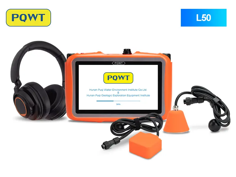
Compact concealed-pipe listening
For comparative acoustic screening and locating beneath floors and inside walls.
View product →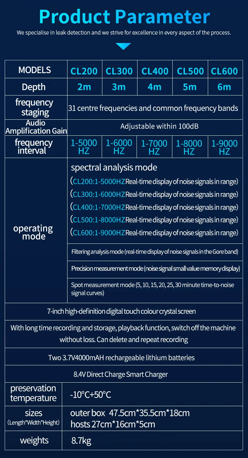
Professional spectrum analysis
For selectable frequency analysis, recording and repeated comparison on pressurized pipelines.
View product →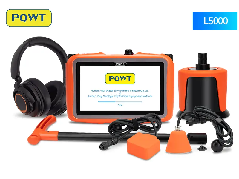
Professional indoor and outdoor locating
For broader technician workflows requiring staged screening, comparison and pinpointing.
View product →Frequently asked questions
What is the most accurate water leak detection method?+
Accuracy depends on the pipe and site. The strongest decision usually comes from two independent methods agreeing, such as abnormal flow plus acoustic pinpointing or section isolation plus tracer gas.
Is tracer gas better than acoustic detection?+
Not universally. Acoustic testing is faster when a pressurized leak produces usable vibration. Tracer gas can be stronger for quiet plastic pipes, very small leaks or isolated systems but requires more preparation.
Can thermal imaging find underground water-main leaks?+
Thermal imaging may show surface temperature effects in favorable conditions, especially in buildings, but it is not a universal underground-main locator and a negative image does not rule out leakage.
What method works best on PVC or HDPE pipe?+
Use closer acoustic spacing and lower-frequency comparison first when pressure is adequate. If the signal remains weak, tracer gas or correlation configured for the correct plastic pipe may be more useful.
Do I need to know the pipe route before pinpointing a leak?+
Yes. A wrong route can turn a valid signal into the wrong excavation point. Use plans, access points or a suitable utility locator to confirm the route before detailed testing.
Can GPR detect a water leak directly?+
Usually not. GPR may show a buried pipe, trench, void or moisture-related change. Confirm the leak point with flow, pressure, acoustic, correlation, tracer-gas or inspection evidence.
PROJECT REVIEW & MODEL SELECTION
Match the method before choosing the model
Send the pipe material, diameter, operating pressure, burial depth, surface, route length, access points and symptoms. We will compare suitable detection workflows and equipment configurations.