Do not walk an entire long pipeline and chase the loudest sound. First confirm abnormal water loss, map the pipe and divide the route into manageable zones using meters, valves, branches or temporary flow and pressure checks. Screen accessible fittings, loggers or correlation points to identify the strongest section. Then ground-listen that shorter section with consistent spacing and settings. Use tracer gas or another independent method when plastic pipe, low pressure, deep burial or noise makes the acoustic evidence weak. Excavate only after the suspected zone is repeatable and supported by more than one observation.
A leak on a 20-metre service pipe and a leak on a multi-kilometre transmission or distribution line are not the same search problem. On a long route, the first job is not pinpointing. It is reducing uncertainty: which branch, pressure zone or interval is losing water, and which parts can be excluded before detailed listening begins?
Professional long-pipeline surveys combine network information with field measurements. Flow imbalance, pressure behavior, valve isolation, acoustic screening, noise logging, correlation, ground microphones and tracer gas each answer a different question. The fastest workflow is usually the one that uses the right method at the right scale and records why each test section was selected.
Why long pipelines need a staged leak-detection strategy
A single sensor reading represents only one location and one moment. On a long pipeline, pressure changes, branches, pumps, road crossings, pipe repairs and mixed materials can create several unrelated sound zones. Searching every metre with the same detailed method wastes time and increases the chance of following background noise.
A staged survey moves from large scale to small scale. The first stage confirms that a real loss exists. The second identifies the likely branch or interval. The third compares closely spaced points inside that interval. The final stage cross-checks the excavation zone. This hierarchy is useful whether the route serves a municipality, factory, farm, campus or long private property.
Confirm the loss
Use meter, flow, pressure and consumption evidence to separate leakage from legitimate demand or instrumentation error.
Localize the section
Use valves, branches, district meters, loggers, correlation points or controlled isolation to reduce the search length.
Pinpoint systematically
Ground-listen or surface-scan the shorter interval with consistent spacing, sensor contact and filter settings.
Verify before excavation
Repeat the peak, approach it from both directions and seek independent flow, pressure, correlation or tracer-gas evidence.
Collect the right pipeline information before field testing
The survey plan should begin with a route map and operating information. If drawings are incomplete, locate the pipe or tracer wire and mark known valves, meters, hydrants, service connections, changes in material and previous repairs. A detector cannot compensate for listening several metres away from the actual alignment.
Record the normal operating pressure and flow pattern, including pumps, tanks, irrigation cycles, production shifts and night demand. A sudden increase in minimum night flow or unexplained pump cycling may support the leak hypothesis, but it does not reveal the exact point by itself.
| Information | Why it matters | Field decision |
|---|---|---|
| Pipe route and length | Defines the real search corridor | Mark bends, branches, crossings and access points |
| Material and diameter | Changes vibration transmission and correlation settings | Separate metal and plastic sections where possible |
| Pressure and flow | Affects leak energy and confirms abnormal loss | Choose a representative operating period |
| Burial depth and surface | Changes ground-sensor coupling | Plan spacing and sensor type for soil, asphalt or concrete |
| Valves and meters | Provide natural section boundaries | Design isolation or comparison zones |
| Noise sources | Pumps, traffic and machinery can imitate leakage | Schedule quiet tests and document equipment operation |
Divide a long water pipeline into manageable test zones
Use existing meters, valves and branches as the first zoning points. Compare inflow with known or estimated consumption when reliable data are available. Where operations permit, a controlled valve step or section isolation can show whether flow or pressure behavior changes, but it must be planned to avoid pressure transients, contamination risk or interruption to critical users.
When fixed data are limited, place temporary acoustic loggers or make repeated contact measurements at valves, hydrants and meters. The objective is not to declare the exact leak from one logger. It is to rank sections and identify where a detailed survey will deliver the most value.
- Start with the largest defensible boundaries, then subdivide only the abnormal zone.
- Compare equivalent time periods so normal demand does not appear as leakage.
- Keep a written record of valve status, pressure, flow and active equipment.
- Do not close an unverified valve or change network pressure without authorization.
- Recheck any zone whose result conflicts with visible flow, pressure or customer-use evidence.
Screen the likely section with contact listening, loggers or correlation
Contact listening at valves, hydrants, meters and exposed fittings can identify which part of the pipe carries a repeatable leak-like signal. Keep gain and frequency settings consistent while comparing points. A loud mechanical source at one valve should not be treated as a leak until the signal pattern is checked along the pipe and under a changed operating condition.
A leak noise correlator compares signals recorded at two known points and estimates the probable position between them using the separation distance, pipe material and diameter. It is especially useful when suitable contact points bracket the suspected section. Incorrect pipe data, multiple leaks, branches, plastic attenuation and poor sensor coupling can reduce confidence, so the calculated point still needs ground verification.
| Screening method | Best use | Important limitation |
|---|---|---|
| Contact listening | Fast comparison at accessible fittings | Signal may travel from a pump, valve or another line |
| Noise loggers | Ranking sections over quiet overnight periods | A logger flags persistent noise, not a guaranteed leak |
| Leak correlation | Estimating position between two known contact points | Requires accurate pipe data and usable signals at both sensors |
| Flow and pressure checks | Confirming which zone behaves abnormally | Demand variation can mask or imitate leakage |
| Visual inspection | Finding washout, wet soil or structural effects | Water can migrate far from the actual defect |
Pinpoint the suspected leak with repeatable ground measurements
Once the search has been reduced to a practical interval, mark the pipe route and take ground or surface readings at regular spacing. Use the same sensor, contact pressure, gain and filter band for each comparison. Move past the strongest point in both directions; a real leak zone should be bracketed by weaker neighboring measurements rather than defined by one isolated high value.
Reduce spacing around a stable peak and repeat after a pause or at a quieter time. For plastic pipe, very small leaks, low pressure or deep burial, the usable acoustic zone may be narrow or absent. Tracer gas can provide an independent signal when the line can be safely isolated and tested by trained personnel. Gas concentration at the surface can also be shifted by wind, soil, ducts or membranes, so repeated scanning is still necessary.
- Establish a background reference away from the suspected section.
- Measure the mapped route at consistent intervals and record every point.
- Bracket the strongest repeatable zone from both directions.
- Change only one variable at a time when comparing filters or sensors.
- Repeat the suspected point under a different noise or operating condition.
- Use correlation, tracer gas, pressure or controlled exposure when confidence remains low.
How pipe material and site conditions change the survey
Mixed-material networks should be divided at known transitions because signal behavior and correlation velocity can change sharply. The wettest surface point is also not necessarily the defect: leaked water may follow bedding, a service trench, foundation edge or utility duct before becoming visible.
| Condition | Typical effect | Practical response |
|---|---|---|
| Steel or ductile iron | Often carries pipe-borne vibration farther | Screen accessible fittings before close ground listening |
| PVC, PE or HDPE | Attenuates vibration and may shorten the useful distance | Use closer spacing, stable pressure and consider tracer gas |
| Large diameter | May produce complex or lower-frequency behavior | Use accurate pipe data and compare more than one method |
| Soft or wet soil | Can absorb or redistribute ground-borne energy | Improve sensor coupling and reduce spacing |
| Concrete or asphalt | Can couple vibration but also carry traffic and machinery | Test during quiet periods and compare adjacent points |
| Deep burial | Weakens the surface signal | Rely more on sectioning, contact points and independent verification |
Complete field workflow for a long underground pipeline
Confirm abnormal loss
Review meter, minimum-flow, pressure and pump data; exclude legitimate consumption and faulty instrumentation.
Map the network
Mark route, material, diameter, valves, branches, depth, surfaces, access points and known repairs.
Build test zones
Use meters, valves, branches or temporary monitoring points to rank large sections.
Screen contact points
Compare fittings with stable settings or use loggers during representative quiet periods.
Correlate when suitable
Enter verified pipe data, bracket the section with sensors and treat the result as a target for confirmation.
Ground-listen the shortlist
Measure only the likely interval with regular spacing and controlled sensor contact.
Apply a second method
Use tracer gas, pressure isolation, thermal evidence or targeted inspection when acoustic evidence is weak.
Verify and document
Record the confidence zone, evidence, settings and repair outcome, then confirm that abnormal loss has stopped.
Which PQWT leak detector fits the project scale?
Choose equipment from the length of the section that remains after zoning, the available contact points, pipe material, surface and operator workflow. A compact detector may be efficient for a short service connection, while a professional spectrum or multi-sensor system is better suited to repeated municipal, industrial and mixed-surface work. Confirm the final configuration and accessories in the formal quotation.
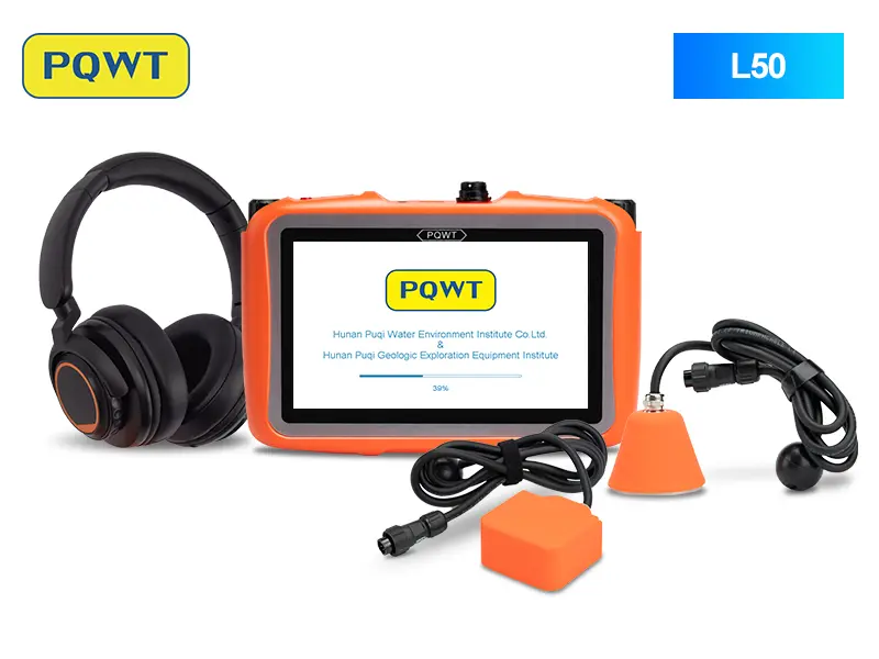
Short service lines and concealed pipes
A compact acoustic option for indoor work, yards and shorter pressurized sections after the route has been narrowed.
View product →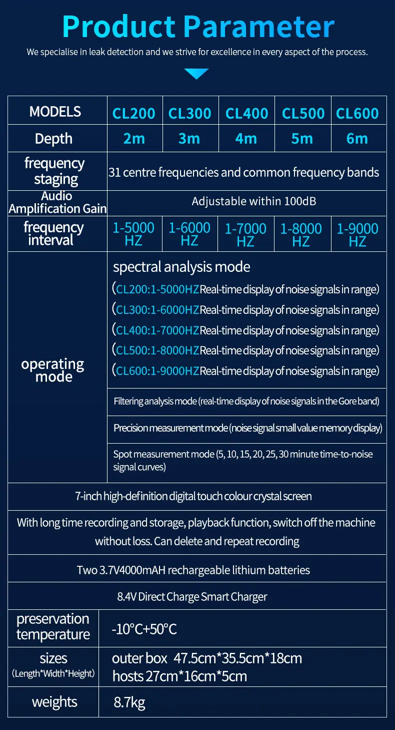
Frequency-led professional comparison
For technicians who need spectrum review, selectable filtering, recording and documented comparison along a pipeline section.
View product →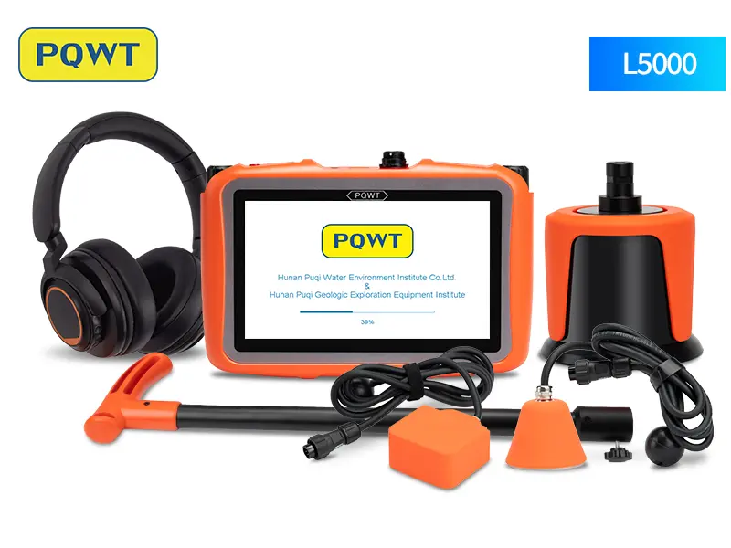
Multi-sensor indoor and outdoor workflow
For mixed projects that require contact, floor and outdoor ground listening after network screening.
View product →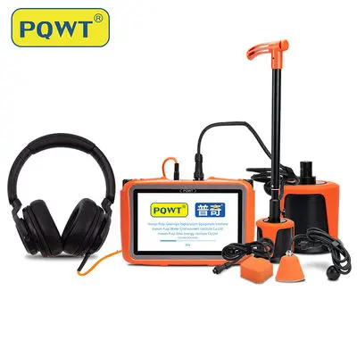
Broader mixed-surface sensor coverage
For professional teams working across varied access points, surfaces and background-noise conditions.
View product →Sources and editorial note
Written as an original technical guide using the source material below. Product suitability and field results still depend on site conditions, operator technique and independent verification.
- US EPA — Control and Mitigation of Drinking Water Losses in Distribution Systems — Overview of water-loss control, district monitoring and acoustic, thermal, tracer and other detection approaches.
- US EPA — Water Audits and Water Loss Control for Public Water Systems — Describes the role of billing, flow monitoring, inspection and leak-detection equipment in locating losses.
- UK Government — Active Leakage Control technical paper — Public technical guidance on active leakage control and systematic network scanning.
Frequently asked questions
What is the fastest way to find a leak on a long water pipeline?+
First reduce the route with flow, pressure, valve zones, contact listening, loggers or correlation. Detailed ground listening should focus on the abnormal interval instead of covering the entire line at close spacing.
Can one acoustic detector locate a leak several kilometres away?+
A handheld detector measures at the sensor location; it does not directly scan kilometres from one point. Long routes should be divided into sections, screened at accessible points and then pinpointed within the most likely interval.
When should a leak noise correlator be used?+
Use correlation when two suitable contact points bracket the suspected section and the material, diameter and distance are known. Verify the calculated position with ground listening or another method before excavation.
What if the long pipeline is PVC or HDPE?+
Plastic attenuates vibration, so use closer contact and ground spacing, stable pressure and accurate route information. Tracer gas or another method may be needed when the acoustic signal is weak.
What information is needed for a detector recommendation?+
Provide the country, pipe material, diameter, operating pressure, burial depth, route length, surface, available valves or meters, background noise, suspected leak symptoms and required quantity.
PROJECT REVIEW & MODEL SELECTION
Send your pipeline data for a model recommendation
Provide the country, pipe material, diameter, pressure, burial depth, route length, surface, access points and background noise. We will compare L50, CL200, L5000 and L7000 for the actual project.