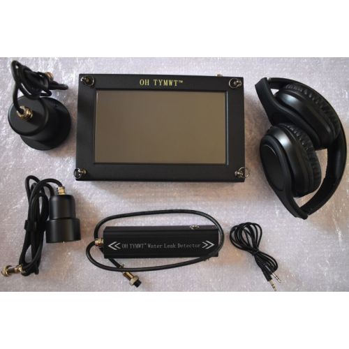
First confirm that water is being lost, isolate ordinary water use and map the probable pipe route. Then build a quiet acoustic baseline and compare a grid of floor points with the same sensor, gain, filter, contact pressure and listening time. Narrow around a repeatable peak from at least two directions, but verify it with pressure, flow, moisture, thermal or tracer-gas evidence before cutting the concrete.
A damp tile, warm patch or high water bill can suggest a concealed leak, but none identifies the pipe opening by itself. Water may migrate along a membrane, screed joint or service channel before it becomes visible. Sound can also travel through concrete and peak at a fitting or structural boundary away from the source.
The safest workflow separates three questions: Is there an active leak? Which pipe section is responsible? Where is the smallest defensible repair zone? Acoustic listening is valuable for the third question when the line is pressurized and the leak produces a repeatable signal, but it should be interpreted with the route and at least one independent check.
Signs of a possible water leak below concrete
Before testing the slab, exclude visible fixtures, toilet valves, water heaters, irrigation branches, drains and appliance connections. These common sources can create the same billing or moisture symptoms as a buried supply-pipe leak.
Meter movement or higher bills
Unexpected continuous use after fixtures and appliances are isolated is stronger evidence than one surface stain.
Pressure loss
A pressurized section that cannot hold a safe test pressure may be leaking, although the test does not locate the opening.
Damp, warm or damaged flooring
Moisture, efflorescence, loose tiles or a warm zone can support the diagnosis, but water and heat may migrate.
Hiss or flow noise
A stable sound when normal use is stopped may justify a structured acoustic survey along the concealed route.
Confirm that an active leak exists
Stop normal demand
Turn off faucets, appliances, irrigation and other legitimate water uses. Follow local safety rules before isolating any process, heating or fire-protection line.
Observe the meter or flow
Record the meter or flow indicator, wait without using water and check it again. Movement supports an active loss but does not identify its location.
Separate branches
Where valves permit, isolate sections one at a time and note which action changes the meter, pressure or sound. Do not operate an unknown valve without authorization.
Record operating pressure
Acoustic energy depends on active leakage. Record normal pressure and avoid exceeding the safe rating of the pipe or system.
Map the concealed pipe before interpreting sound
Use drawings, visible risers, manifolds, valves, room layout and an appropriate utility locator to estimate the route. Mark branches, elbows, fittings, wall transitions and changes in material. These points can transmit or concentrate vibration and should not automatically be labelled as leaks.
Create a simple floor sketch and number each listening point. If the route is uncertain, survey a wider grid first; once the route is credible, compare points along it at regular spacing.
| Record | Why it changes the survey | Useful field detail |
|---|---|---|
| Pipe material | Copper, steel, PVC, PPR, PE and multilayer pipe transmit leak vibration differently. | Material and any known transitions |
| Pipe diameter | Diameter and wall construction affect resonance and signal propagation. | Outside diameter or nominal size |
| Pressure | Low or intermittent pressure can weaken the acoustic signal. | Normal and test pressure |
| Concrete build-up | Tile, screed, insulation, membrane and slab create multiple signal paths. | Finish and estimated concealment depth |
| Route and length | A long or branched route needs more screening points. | Sketch, valves and accessible contact points |
| Noise sources | Pumps, drains, HVAC, traffic and electrical equipment can mimic leak noise. | Source and quiet testing window |
Step-by-step acoustic search under a concrete floor
Choose stable sensor contact
Use a floor sensor that sits firmly on the finish. Clean loose debris and keep the same orientation and contact method at every point.
Create a quiet baseline
Listen at two or more control points away from the suspected zone. Set a usable gain and filter without saturating the display.
Screen a regular grid
Measure fixed intervals along the mapped route. Keep gain, volume, filter, listening time and contact pressure unchanged within the comparison.
Log sound and spectrum
Record both the level and character of the sound. A one-time spike is weaker evidence than a stable broadband or tonal change that repeats.
Shorten the spacing
Around a persistent change, halve the interval and measure beyond it in both directions. The candidate zone should be bracketed by weaker controls.
Repeat from another direction
Cross the route or return in the reverse direction. A credible zone should remain focused instead of following the operator.
Change one condition
If permitted, repeat during a quieter period or after a controlled isolation change. Change only one variable so the result remains interpretable.
Mark a confidence zone
Report a probable area with the evidence and uncertainty—not a single guaranteed dot—until another method supports the location.
What a useful acoustic pattern looks like
More gain is not automatically better. Excessive amplification raises room and structural noise together with the leak signal. The objective is a repeatable contrast between comparable points, not the largest number on the screen.
| Observed pattern | Possible interpretation | Next action |
|---|---|---|
| One isolated, non-repeatable spike | Impact, sensor movement, speech or transient equipment noise | Repeat the point and adjacent controls |
| Broadly loud across the whole slab | High gain, structural vibration, pump or flowing branch | Lower gain, stop controllable noise and test contact points |
| Strongest at a valve or fitting | Leak vibration may travel along the pipe, or the fitting itself may generate turbulence | Compare both sides and use another verification method |
| Repeatable focused maximum with weaker points around it | A probable leak zone consistent with the route | Bracket the zone, repeat and verify independently |
| No stable acoustic change | Small leak, low pressure, plastic pipe, deep or soft layers, or no active leak | Review diagnosis and consider tracer gas, pressure testing or moisture mapping |
Verify the probable zone before breaking concrete
- Repeat the acoustic survey at a different time or after a permitted isolation change.
- Check whether the water meter or measured flow responds when the suspected branch is isolated.
- Use an appropriate pressure test to confirm section leakage without exceeding safe limits.
- Map moisture or temperature patterns, while remembering that water and heat can move away from the opening.
- Use tracer gas when plastic pipe, low pressure, small leakage or background noise prevents a stable acoustic result.
- Use a small controlled inspection opening only after utility clearance and a documented risk assessment.
Choose the detector around the floor and workflow
A model recommendation should consider the pipe and site, not only a stated depth. Ask the supplier to confirm sensor configuration, included accessories, training, warranty and a test procedure that resembles the actual floor.
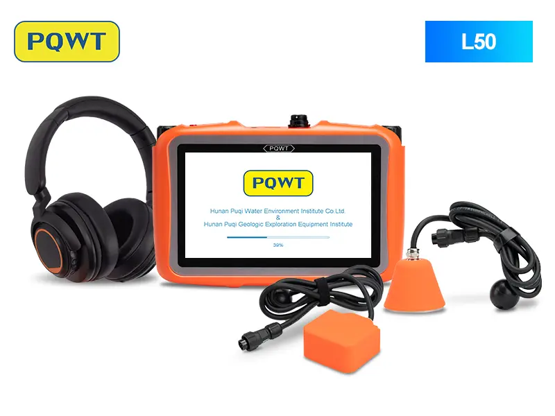
Compact concealed-pipe screening
Triangular and square sensor options for floors, walls, cabinets and indoor pressure-pipe comparisons.
View product →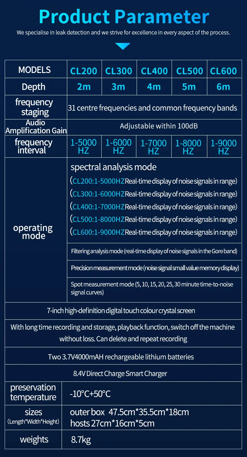
Professional spectrum-led analysis
Selectable frequencies, filtering, recording and playback for technicians comparing pipe and floor signals.
View product →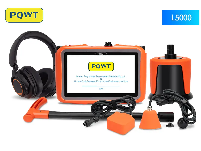
Multi-sensor indoor and outdoor projects
A three-sensor workflow for mixed floor, wall and buried-pipeline conditions.
View product →Send these details for a detector recommendation
These details let the sales and technical team compare L50, CL200, L5000 or another method around the real project. A formal quotation should confirm the selected model, sensors, accessories, export price, delivery, remote guidance and warranty.
- Country and whether the site is a house, apartment, hotel, hospital, factory or other building.
- Pipe material, diameter, estimated age and any known material changes.
- Normal operating pressure and whether the suspected branch can be isolated.
- Floor finish, concrete or screed build-up and estimated concealment depth.
- Approximate pipeline length, route sketch, branches and accessible valves or fittings.
- Symptoms: meter movement, pressure loss, dampness, heat, sound and when the problem began.
- Background noise, available testing time, photos and previous inspection results.
Sources and editorial note
Written as an original technical guide using the source material below. Product suitability and field results still depend on site conditions, operator technique and independent verification.
- US EPA WaterSense — Home Maintenance: Leaks — Meter, usage and household leak-check guidance.
- On the Acoustic Filtering of the Pipe and Sensor in a Buried Plastic Water Pipe — Experimental research on pipe, sensor and acoustic transmission effects.
Frequently asked questions
Can a water leak detector see through concrete?+
No. An acoustic detector listens for vibration and leak noise that reaches the sensor through the pipe and structure. It compares signals; it does not create an image of the pipe opening.
Can I find a slab leak without breaking the floor?+
You can often narrow a probable zone non-destructively with meter checks, route mapping, acoustic comparison, moisture or thermal evidence and tracer gas. A repair may still require controlled access after the location is verified.
Does the loudest point always mark the leak?+
No. Concrete, fittings, voids and structural elements can carry or concentrate sound. Repeat the point, compare both directions and verify with another type of evidence.
Why is a plastic pipe leak difficult to hear?+
PVC, PPR, PE and similar materials often attenuate vibration more than rigid metal. Low pressure, small leakage and soft construction layers can weaken the signal further, so shorter spacing or tracer gas may be needed.
Which PQWT detector is suitable for an indoor concrete floor?+
L50 is a compact option for concealed indoor pressure pipes. CL200 adds professional frequency and spectrum tools, while L5000 supports a broader multi-sensor indoor and outdoor workflow. Suitability depends on the pipe, pressure, depth, surface and noise.
What information is needed before choosing a model?+
Send the country, pipe material, diameter, pressure, concealment depth, floor finish, route length, noise conditions, symptoms and photos or a route sketch.
PROJECT REVIEW & MODEL SELECTION
Send your concrete-floor leak project for a model check
Include the country, pipe material, diameter, pressure, concealment depth, floor finish, route length and suspected area. We will compare the suitable detector, sensor package, warranty, shipping and current export quotation.