Select GT150A, GT300A, GT500A or GT1500A from the realistic target depth, local geology, survey area, drilling capability and interpretation support. The stated survey range is not a guarantee that water exists at that depth and does not directly predict water yield. Use nearby well logs, repeat lines, cross-lines and geological controls, then verify the target by drilling logs and a pumping test.
The PQWT GT series is presented as a group of multi-channel geological survey configurations for groundwater target screening. The models mainly differ in stated range and field configuration, but a deeper model is not automatically the better economic or geological choice.
A good selection begins with the drilling decision the survey must support: the likely aquifer depth, formation changes, access, available well records and the cost of testing an uncertain target.
GT150A, GT300A, GT500A and GT1500A compared
| Model | Stated survey range | Field configuration | Typical selection question |
|---|---|---|---|
| PQWT-GT150A | Up to 150 m | High-resolution multi-channel field system | Are the expected targets and drilling plan mainly within a shallow-to-medium range? |
| PQWT-GT300A | Up to 300 m | Multi-channel system with 22-electrode field configuration | Does the project need additional range while remaining within practical drilling depth? |
| PQWT-GT500A | Up to 500 m | High-resolution acquisition with 10.1-inch field display | Are deeper structures plausible and supported by nearby geology or well records? |
| PQWT-GT1500A | Up to 1,500 m | Deep-range 18-channel configuration with field rod and cable set | Does a large professional project justify deep-range acquisition and specialist interpretation? |
How to choose the correct stated survey range
Expected aquifer depth
Use nearby wells, geological maps and drilling experience to define a realistic depth window before selecting equipment.
Practical rig capacity
Do not pay for a range far beyond what the available rig, budget and casing program can test.
Structure and contrast
Electrical responses are indirect and may reflect lithology, clay, salinity, fractures, moisture or interference—not only groundwater.
Cost of a wrong target
Higher-cost drilling decisions need stronger controls, cross-lines, independent interpretation and documented uncertainty.
A responsible GT groundwater survey workflow
Collect existing evidence
Gather well logs, water levels, drilling results, geology, topography, land access and cultural interference before field work.
Define a geological question
Design each line to cross a suspected structure or compare one geological condition with another.
Use consistent acquisition
Keep electrode spacing, direction, point interval and operating procedure consistent enough for valid profile comparison.
Run repeat and cross-lines
A credible anomaly should be repeatable and, where possible, supported by a crossing line rather than one isolated profile.
Review alternative explanations
Check whether clay, salinity, utilities, power lines, surface conditions or terrain could produce the response.
Rank targets with uncertainty
Present more than a colored image: document the baseline, anomaly, control evidence, confidence and remaining risks.
Verify after drilling
Record lithology, fractures, water strikes, static level and construction. Use a pumping test to establish sustainable yield.
What a GT survey can and cannot establish
| Survey output | Responsible interpretation |
|---|---|
| Curve or profile anomaly | A change in measured response that requires geological interpretation |
| Repeatable low or high zone | A target for further investigation, not automatic proof of water |
| Recommended drilling point | A ranked location based on available surface evidence and stated assumptions |
| Water depth | Must ultimately be confirmed by drilling and borehole records |
| Water yield | Cannot be directly guaranteed by a surface electrical survey; verify with a pumping test |
| Water quality | Requires sampling and laboratory analysis |
Use drilling and pumping data to close the evidence loop
- Record every lithological change and drilling depth.
- Note fracture zones, water strikes and losses during drilling.
- Measure static water level after the borehole stabilizes.
- Run a controlled pumping test and record drawdown and recovery.
- Analyze water quality for the intended domestic, agricultural or industrial use.
- Compare the verified outcome with the survey interpretation to improve future local decisions.
Send these details for a GT model recommendation
| Information | Why it is needed |
|---|---|
| Country and exact project area | Provides geological and shipping context |
| Target drilling depth | Narrows the useful GT range |
| Nearby well logs and yields | Shows what is locally plausible and what remains uncertain |
| Known geology | Supports line design and interpretation |
| Survey area and access | Determines practical line length and field configuration |
| Drilling rig capacity | Keeps the recommendation aligned with what can be verified |
| Operator experience and language | Defines training and interpretation support |
Review the PQWT GT series product pages
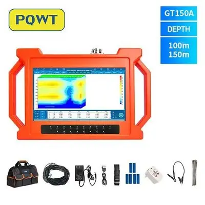
150 m multi-channel configuration
For projects with a realistic shallow-to-medium target range.
View product →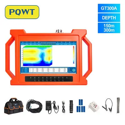
300 m multi-channel configuration
For projects requiring additional range and a 22-electrode field setup.
View product →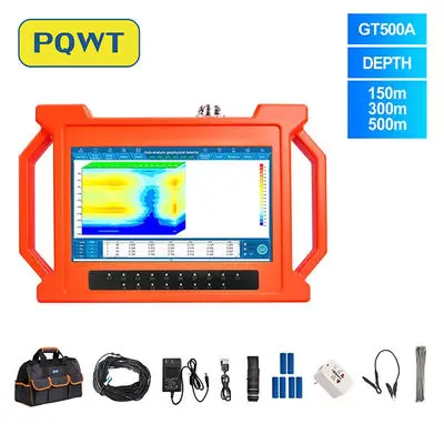
500 m multi-channel configuration
For deeper target screening supported by geology and professional interpretation.
View product →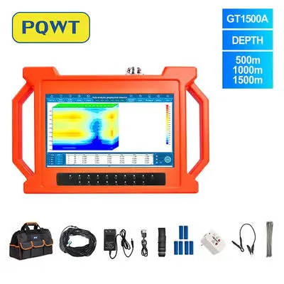
Deep-range multi-channel configuration
For large professional projects with deep geological questions and verification capacity.
View product →Frequently asked questions
Which PQWT GT model should I choose for a 200 m drilling plan?+
GT300A is the first range to review, but model selection should also consider geology, nearby wells, survey area and the rig's practical verification depth.
Does GT1500A guarantee water at 1,500 m?+
No. The stated range does not prove that water exists, is drillable or will provide a sustainable yield at that depth.
Can a GT detector directly measure water yield?+
No surface electrical survey should be treated as a direct pumping-yield measurement. Sustainable yield is established after drilling through a controlled pumping test.
Why are cross-lines important?+
They test whether an anomaly is spatially repeatable and help distinguish a possible geological structure from one-line noise or interference.
Can clay or salinity resemble a groundwater anomaly?+
Yes. Electrical responses can be influenced by clay, salinity, lithology, fractures, moisture and cultural interference, so alternative explanations must be reviewed.
What training information should I request?+
Ask about field setup, electrode spacing, line design, repeat measurements, profile interpretation, interference checks, report preparation and post-drilling verification.
PROJECT REVIEW & MODEL SELECTION
Request a GT series project review
Send the project country, expected geology, target depth, nearby well information, survey area and drilling capacity. We will compare GT150A, GT300A, GT500A and GT1500A and confirm the current configuration and quotation.